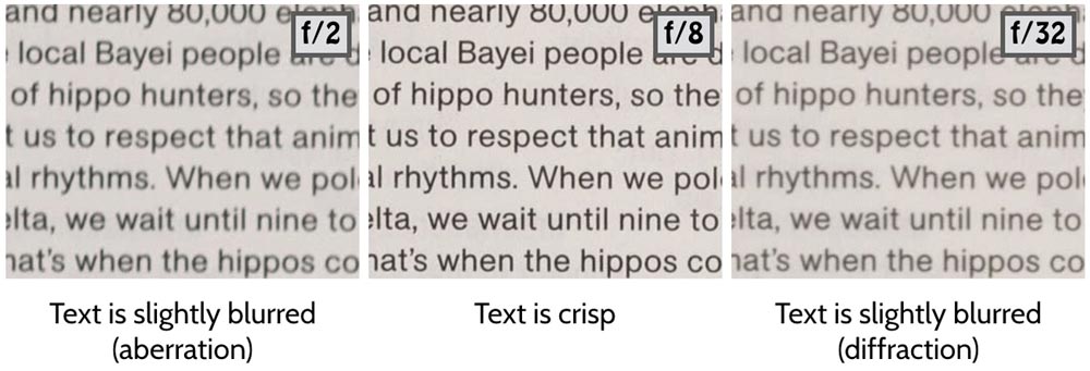
The effects of diffraction can be seen in the right-hand image below (point of focus was identical in all shots). Here we see that, relative to ƒ/8 the text at ƒ/32 is less sharp.
 For photographers, the issue is that we sometimes need this high aperture to widen the depth of field and have both foreground and background in focus (typical for wide-angle, landscape shots). In fact, we do so at the expense of sharpness in the plane of focus.
What is diffraction?
(It helps to have an understanding of the electromagnetic spectrum and its properties before reading the below).
Diffraction is not just a phenomenon specific to photography. It occurs whenever transverse waves move through a gap sufficiently small relative to their wavelength. The observable effect is that the light is seen to “bend” around the obstruction and this spreading results in an image larger than would otherwise be expected. We can see this in the fringing observed at the edge of shadows, for example.
In photography it is a concern because it makes the point of focus less than optimally sharp for a given lens. Consequently, it is usually tolerated as compromise for a greater depth of field or a longer shutter speed. But why do we lose sharpness when we stop down? Fortunately, we can begin to understand this phenomenon armed with only basic high school trigonometry.
Why does it occur?
In its most basic form a lens is simply a hole through which light travels before hitting the sensor. In a 2D world (which we will use to explain diffraction) this would be illustrated by a simple slit in a wall. Before we proceed, however, we must acknowledge one physical property: when a transverse wave moves through a slit or gap (an aperture) it can be treated as if each point in the aperture acts as a point source from where a new wave spreads. Aperture comes from the Latin apertura which simply means “an opening”. Let’s assume we have:
- only one, distant monochromatic (only one wavelength) light source
- an aperture of width a, where a is only slightly larger than λ (wavelength of the light)
- a sensor which is a distance D from the gap, where D >> a
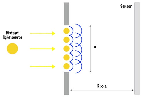
Note that the waves from the distant light source will propagate 360° but only a small slither of these will pass through our aperture in much the same way that if you look at a star only an inconceivably small amount of the light waves emitted will actually pass through your pupil. Moreover, because the light source is distant we can assume that these waves will approach in straight lines, parallel to each other.
In between our gap we have five sources from which the waves propagate (obviously, a small number is chosen for the sake of explanation). First, let’s look at the new waves from each source point that travel on in the same direction i.e. the axis of the wave is travelling in a horizontal line perpendicular to the sensor.
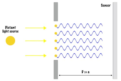
Electromagnetic waves (and so light waves) are addictive and so since we now have all five waves travelling in phase and in the same direction the resulting effect is constructive interference and we have a wave of maximum possible amplitude. And because the intensity of light is proportional to the square of its amplitude this also results in the maximum possible intensity of light hitting our sensor.
To look at light waves in other directions, let’s define θ to be the angle between the original direction of travel for our light wave and the direction of travel of the wave from the source point.
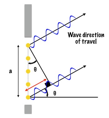
Trigonometry tells us that the red line in the diagram has length a sin θ. We’ve already looked at the case when θ = 0 degrees (waves in phase going in the same direction). Now we look at a special case when a sin θ = λ as in the diagram below.
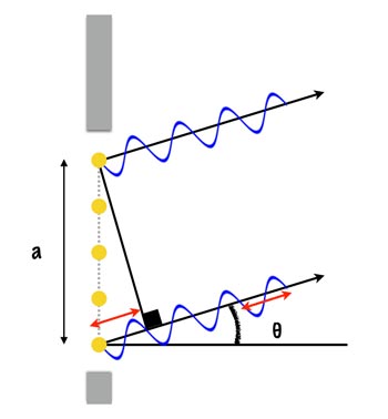
What we see here is that, like when θ = 0, from the point where we have our right-angle symbol the waves are once again in phase and travelling in the same direction (and so constructive interference occurs). But the implication of this is that at a/2 we have the following:
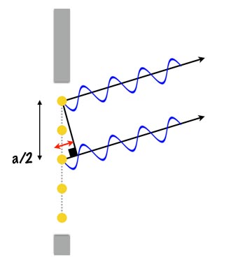
Here the difference between the phase of the top wavelength and the bottom wavelength is λ/2 and so they interfere destructively entirely cancelling each other out—no light will hit the sensor along this plane!
Now to get an idea of what’s happening on a bigger scale, imagine that instead of just 5 source points with have 2,000 (2k) evenly spaced source points in the aperture. Counting from top to bottom, we have 1 to k above the mid-point and k+1 to 2k below.
Similar to above when a sin θ = λ waves 1 and k+1 are out of phase by λ/2 and cancel each other out and the same goes for 2 and k+2, 3 and k+3 and so on all the way down to k and 2k.
This is the case for waves travelling “upwards” in our 2D world, but this experiment is symmetrical around the axis between the mid-point of the aperture and the mid-point of the sensor and so we would see all these minimums at the same angle in the “downwards” direction, too.
Note further that we are not limited to one angle for a minimum. There would also be minimums at a sin θ = 2λ, a sin θ = 3λ, etc. giving us a sin θ = mλ (where m = 1, 2, 3…) [equation 1] as our range of minimums.
So we have a maximum light intensity at θ = 0 and a zero light intensity at a sin θ = λ and (re-arranging equation 1) we get the angle of the minimums to be θ = sin-1 (mλ / a). As you can probably imagine, as θ increases from zero we observe steady decreases and increases in light intensity (as the waves gradually become out of phase and then back in phase again) and the resulting pattern of light intensity for the above experiment would look like this:
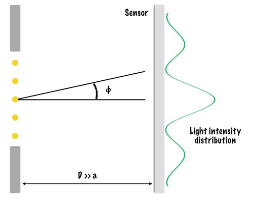
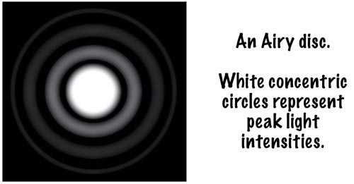
And which can be directly related to the same effect in 3D…
Finally, one more piece of trigonometry:
Let y be the distance between the central maximum and the first minimum. We then have:
tan θ = y / D
Realising that θ will in reality be a very small angle and remembering the shape of the cosine curve we can see that for small θ, cos θ ~ 1.
Now…
tan θ = sin θ / cos θ
… so for very small θ we have:
tan θ = sin θ / 1 = sin θ
But we already know sin from our above calculations (equation 1). Substituting we get:
sin θ = mλ / a
tan θ = y / D
⇒
mλ / a = y / D
m =1 (we’re talking about the first minimum). Thus ⇒
λ / a = y / D
⇒
y = λD / a [equation 2]
Moving back into the 3D world this becomes:
y = 1.22 λD / a
(don’t worry about the 1.22—it gets complicated mathematically—just be glad it’s a nice constant)
This equation is critical because it tells us that as we decrease our aperture (a) the distance between the minimums increases (a is inversely proportional to y). The light intensity distribution will therefore be more spread out resulting in a smaller light intensity peak at θ = 0 and it is the peak of greatest light intensity at θ = 0 which the camera ultimately records.
Obviously, the scenario of one, distant light source is not representative of photography. In fact, the light that enters the lens is more likely incident (or reflected) light coming off an infinite number of source points in the frame (leaves, water, an eyelash, ad nauseum). So let’s assume we have two light sources a small distance above the first light source which, for convenience, is assumed to be in the very centre of our image.
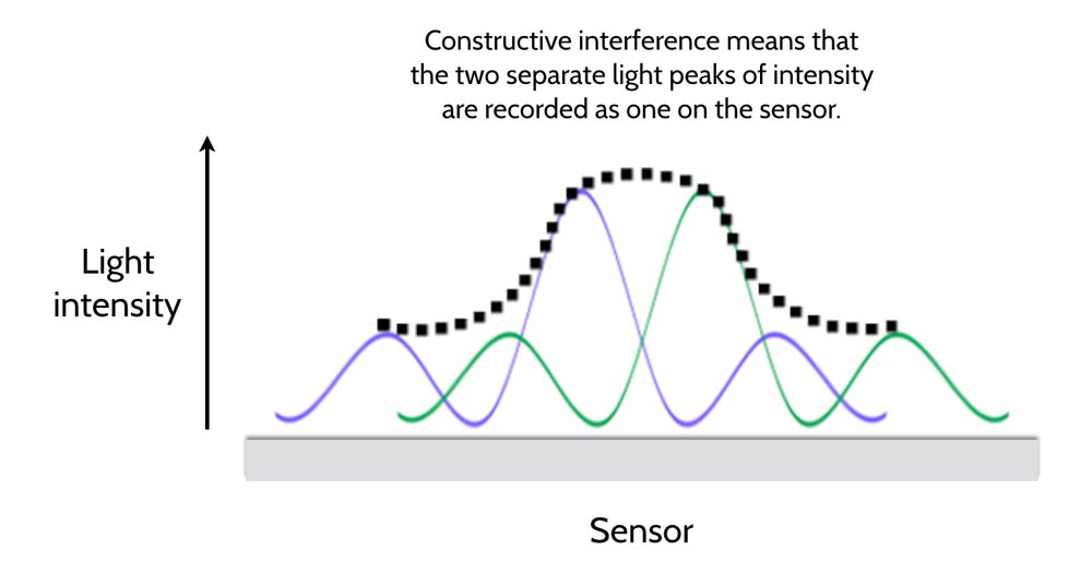
The addition of this second light source doesn’t change the mechanics. You only need to remember that wavelengths are additive so that any overlap will add to the light intensity seen on the sensor. From equation 2 we know that as the aperture increases the peaks at θ = 0 get bigger and the cones slimmer. But as we decrease the aperture (increase the f-number on our camera) the peaks become more “mound-like” and the camera struggles to distinguish one light source from the other when two points get sufficiently close together. This is why at smaller apertures our images become less sharp: the light points very close together cannot be resolved—two separate light intensity points are recorded as one on the sensor like in the diagram below!
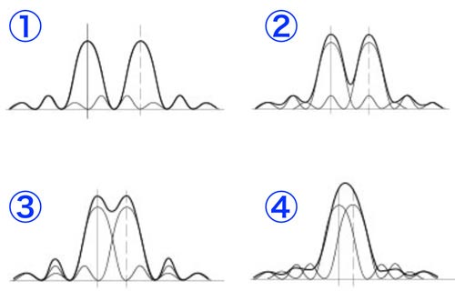
The four graphs below show this happening as two points move closer together (for a fixed aperture). By point 3 the camera would be unable to distinguish between these two points and the resulting image would be less sharp.
In Practice
To give you an idea of scales here, visible light has a wavelength of approximately 400-720nm (“nm” means nanometres with 1nm equivalent to 1 billionth of a metre or 1 millionth of a millimetre). The width of human hair is about 100,000nm.
The relationship between focal length, diameter, and aperture number is given as:
N = f /D
(N is the ƒ/x number we are familiar with seeing on the front of our lenses).
Accordingly, we can easily work out the diameter of the lens for any given aperture with just the focal length.
| f-number | Diameter (mm) |
|---|---|
| 1 | 50.0 |
| 1.4 | 35.7 |
| 2 | 25.0 |
| 2.8 | 17.9 |
| 4 | 12.5 |
| 5.6 | 8.9 |
| 8 | 6.3 |
| 11 | 4.5 |
| 16 | 3.1 |
| 22 | 2.3 |
You may be thinking that in our example we had a ~ λ whereas in actuality the aperture diameter is clearly magnitudes larger than λ. But when we compare an ƒ/8 image with the same image at ƒ/22 we are only observing the onset of diffraction. We have to crop a small part of the images and pixel-peak to see the difference on a monitor. Incidentally, given the above equation, if you were to design a lens capable of a ~ λ it would mean stopping down to approximately ƒ/100,000!
But if a camera’s power of resolution increases with the aperture size, aesthetical effects of changing the depth of focus aside, why aren’t we shooting everything wide open? Why is ƒ/8 generally the optimum aperture for sharpness and not ƒ/2 or below?
Until now we’ve been talking only about a diffraction-limited system. Diffraction is a physical phenomenon not caused by imperfections or misalignments in the lens glass but by the physical properties of light. A system which is said to be diffraction-limited is one where the ability to resolve is limited only by diffraction. Lenses we buy today are not diffraction-limited (and if they were we would not like the price tag). But to understand why shooting wide open can lead to “softer” images we must understand the effects of aberrations.
(The base of this article was adapted from Paul Tipler’s page)